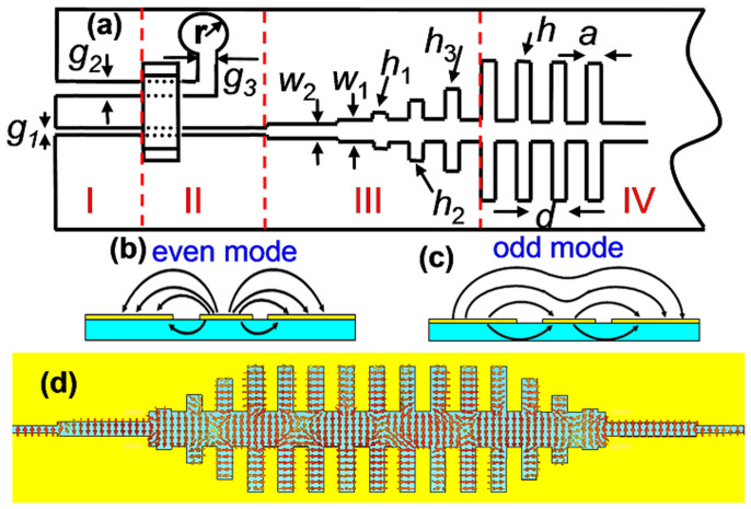
Figure 3.
(a) Schematic picture of odd-mode SPP transitions from an asymmetric coplanar waveguide to the complementary plasmonic waveguide, in which g1 = 0.15 mm and g2 = 0.4 mm are selected in Region I to feed electromagnetic energies from the SMA connector. Region II is used to realize the mode conversion between the asymmetric coplanar waveguide and the slot line, in which an air bridge is employed to suppress the odd mode, and a circular balun with r = 5 mm and g3 = 1 mm is used to absorb the electromagnetic fields in the wider slot. Region III includes the stepped slot lines and gradient grooves, matching the impedance and wave vectors in broadband between the front slot line and SSPP waveguide. Region IV is the complementary plasmonic waveguide, in which the parameters are chosen as w1 = 1 mm, w2 = 0.4 mm, h1 = 0.5 mm, h2 = 2.4 mm, h3 = 4.7 mm, h = 6.5 mm, d = 5.5 mm, and a = 1 mm. (b) and (c) The distributions of electric fields for the even and odd modes in the asymmetric coplanar waveguide. (d) The electric-force lines in the complementary plasmonic waveguide.

