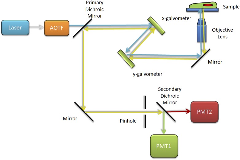
Figure 4.
Basic CLSM light path. Schematic diagram of the CLSM light path with blue excitation light selected by the AOTF. The light is focused onto the sample by the objective lens and then scanned across the sample by the x and y galvanometer mirrors. Emission light is focused by the objective lens, descanned by the mirrors, and reflected toward the detection light path by the primary dichroic mirror. In-focus light is selected by the pinhole aperture. The secondary dichroic mirror splits the green emission light and directs it to be detected by PMT1, and the red emission light passes and is detected by PMT2.

