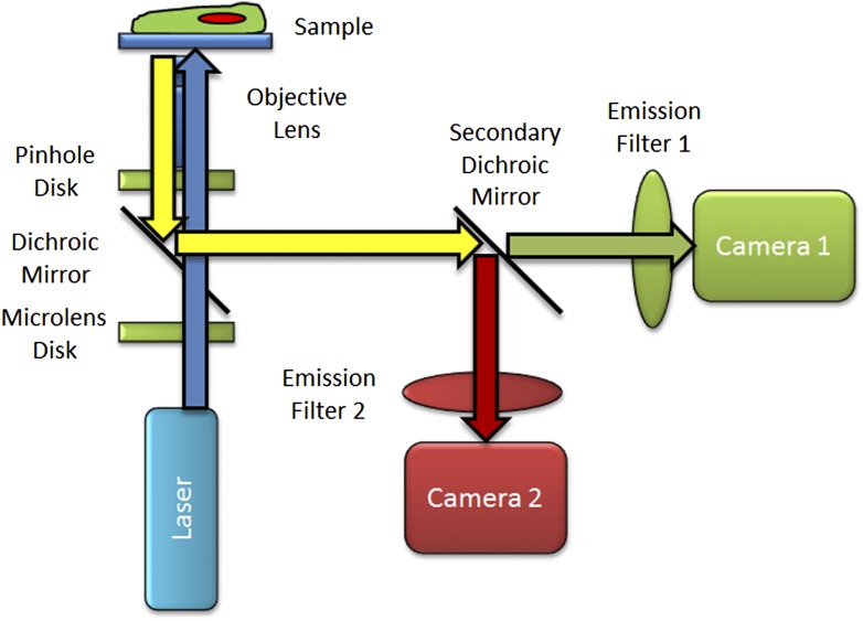
Figure 6.
Basic SDCM light path. Schematic diagram showing blue laser light passing through the microlens array disk and being focused through the dichroic mirror and through the pinhole array disk. These 2 disks along with the dichroic mirror spin as 1 unit. As the disk spins, many laser beam spots are focused onto the sample by the objective lens and are scanned across the sample in the FOV. Emission light from the sample is focused by the objective lens back through the pinhole array disk, is reflected off of the primary dichroic mirror, and split into green and red emission channels by the secondary dichroic mirror. In this example, 2 camera-based detectors are used to generate images of green and red stains.

