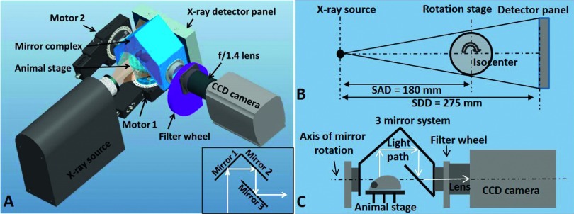
FIG. 1.
Configuration of the integrated x-ray and optical tomography system. (A): Configuration of the integrated imaging system. The inset demonstrates the arrangement of three mirrors. (B): Top view of the CBCT geometry. SAD: source-to-axis distance; SDD: source-to-detector distance. (C): Side view of the optical imaging geometry. Light emitted from the animal surface is reflected through the three-mirror system to the CCD camera. The mirror system can be rotated to capture light at different angles.

