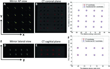
FIG. 7.

Geometrical registration of the optical and CBCT coordinates. (A): Optical image of the phantom when the mirror system is above the stage (vertical position, 0° angle). Sixteen holes were marked and used in the calibration. (B): The coronal slice of the phantom CBCT corresponding to mirror vertical view in A. AP: anterior–posterior. (C): Registration of the optical and CBCT coordinates at mirror 0° position. (D): Optical image of the phantom when the mirror system is at the lateral position (horizontal position, 90°). (E): The sagittal slice of the phantom CBCT corresponding to mirror lateral view in (D). (F): Registration of the two coordinates at mirror 90° position.
