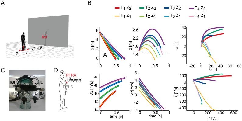
Fig 1. Experimental apparatus, ball trajectories, and marker placement.
(A) Subjects were standing at a distance of 6 m in front of a screen with a hole through which balls were projected by a launching apparatus positioned behind the screen. (B) Ball trajectories in spatial and in gaze coordinates for the different experimental conditions examined in the present study. The different T-Z condition are shown in different colors. Solid thick lines represent the Z2 conditions, thin lines represents Z1 conditions. Top Panels: horizontal (x) and vertical (z) spatial coordinates over time of the average ball trajectory for each block, and the corresponding azimuth and elevation gaze coordinates (rightmost column); the dashed line in the z(t) plot represents the subject eyes height. Bottom Panels: horizontal (x) and vertical (z) spatial velocities of the average ball trajectory for each block, and the corresponding azimuth versus elevation gaze velocities (right most column). (C) Vicon markers placement on the Eyelink helmet. (D) Vicon markers placement on the subject upper trunk.

