
Figure 6.
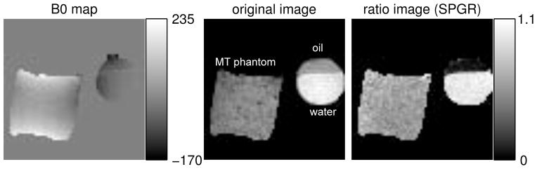
The B0 map and the resulting images of Phantom experiment III. Left: B0 map in Hz; middle: the original SPGR image with FSMT disabled where oil, water and the MT phantom are labeled; right: the ratio image taken between the one with FSMT contrast and the one without.