Figure 1.

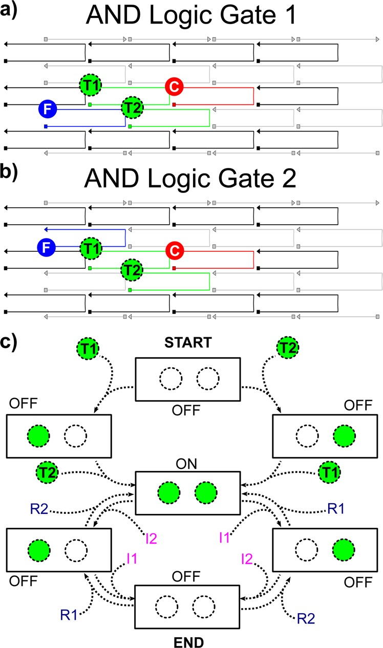
Schematic of (a) AND logic gate 1 and (b) AND logic gate 2 illustrating DNA brick reconfigurability. AND logic gates 1 and 2 only differ by the position of FAM (blue). (c) Schematic of sequentially switchable excitonic AND logic gate operation. Both logic gates are initially fabricated in an OFF-state with only FAM (blue) and Cy5 (red) chromophores attached. When introduced into solution, TAMRA (T1 and T2, green with dashed outline) functionalized ssDNA oligomers hybridize to the corresponding recognition sites (i.e., tethers), switching the gate into an ON-state configuration and generating a fluorescent output signal. Following addition of T1 and T2 to switch the AND gate to the ON-state, invasion strands (I1 and I2) and restoration strands (R1 and R2) are sequentially added to the sample solution to cycle between OFF- (invasion) and ON- (restoration) states.
