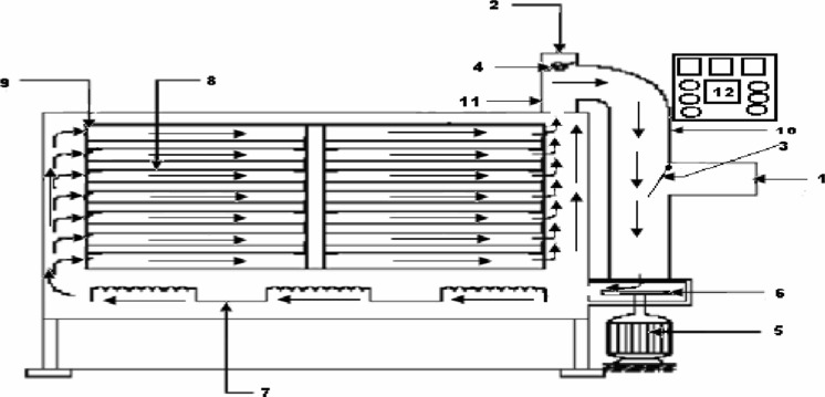
Fig. 1.
Schematic diagram of recirculatory hot-air dryer. (1) Fresh air inlet port (2) Exhaust air outlet port (3) Inlet air flow control flap (4) Exhaust air flow control flap (5) Blower motor (6) Blower (7) Heaters (8) Drying chamber fitted with 12 trays (9) Louvers (10) Exhaust air passage (11) Exhaust air outlet duct (12) Control panel. (Courtesy: Bag SK 2009)

