
Figure 2.
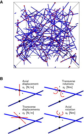
The cross-linked network model. (A) Example of a generated RVE with fibers shown in blue and cross-links in red. (B) A cross-link is a two-node element whose behavior is controlled by four independent spring constants. The cross-link is idealized by coupling the four spring constants to each other, , where is the mean length of the fiber sections. The nondimensional system parameter used in our analysis, compares the cross-link stiffness to the fiber bending stiffness. To see this figure in color, go online.