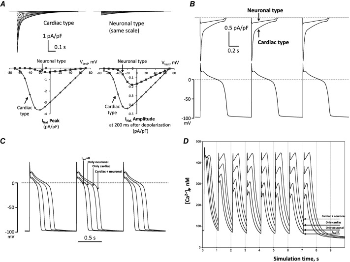
Figure 10.
In silico investigation on neuronal and cardiac INaL components in HF dog ventricular cell
A, predicted current–voltage relationships. The upper panels show families of predicted current traces at different membrane voltages for the cardiac and neuronal Nav components. The lower panels show plotted amplitude values of these predictions. Left lower sub-panel shows the peak INaL (at zero time after the depolarization onset) and right lower sub-panel shows the current amplitudes 200 ms after depolarization onset. Holding potential was Vh = −120 mV, test pulses were applied from –70 mV to +70 mV. B, predicted profile of INaL generated by cardiac and neuronal Navs in numerical model simulations of AP. C and D, predicted differential contribution of INaL by the neuronal and cardiac Navs to shape and duration of AP and intracellular Ca2+ dynamics, respectively, at the pacing rate of 1 Hz. Complete INaL elimination from simulations (INaL = 0) reduces AP duration and eliminates diastolic Ca2+ accumulation. Introduction of only the cardiac or neuronal component of INaL increases AP duration and leads to diastolic Ca2+ accumulation, whereas incorporation of both INaL components, which reflects the situation in situ, affects these physiological responses dramatically. All numerical simulations were performed at a physiological temperature of 37 °C using our modification of the Winslow E–C coupling model of canine failing VCMs (Winslow et al. 1999) with formulations for INaL which were previously developed based on our experimental voltage-clamp data (Undrovinas et al. 2010; Mishra et al. 2011). In the present study INaL formulations included two separate INaL components for cardiac and neuronal isoforms, respectively. Each component has its own activation and inactivation gating variables evaluated from patch-clamp data obtained in the present study (see section ‘Patch-clamp data’).

