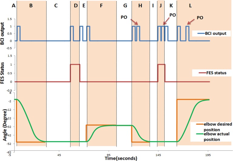
Figure 5.
Time course of the system response for P05. The following data were recorded in real-time: the BCI output: rest (“0”) or activate (“1”); the FES status: deactivate (“0”) or activate (“1”); and the angular position of the exoskeleton. This figure demonstrates a typical behavior of the system. It consists of 12 regions denoted by letters from “A” to “L.” Section “A” describes the start of the trial till triggering the elbow extension, which initiates elbow extension from the initial position; Section “B” (Phase 1) describes elbow extension (to reach the cup); In Section “C,” the participant generates the trigger to activate the FES (to open the hand, Phase 2) and adjusts the shoulder/trunk (Phase 3); In Section “D,” the participant is supposed to generate a trigger to deactivate the FES (to close the hand and grasp, Phase 4); In Section “E,” the participant is supposed to generate a trigger to initiate the elbow flexion; Section “F” elbow flexion (to elevate the cup, Phase 5); In Section “G,” the participant is supposed to generate a trigger for elbow extension and adjusts the shoulder/trunk (Phase 6); Section “H” elbow extension (to place down the cup, Phase 7); In Section “I” the participant is supposed to generate a trigger to activate the FES (to open the hand and leave the cup, Phase 8); Section “J” describes the section in which the participant moves her/his shoulder/trunk away from the cup (Phase 9), and is supposed to generate a trigger to deactivate the FES (to close the hand, Phase 10); in Section “K” the participant is supposed to generate a trigger to initiate the elbow flexion; and Section “L” elbow flexion (to return to initial position, Phase 11).

