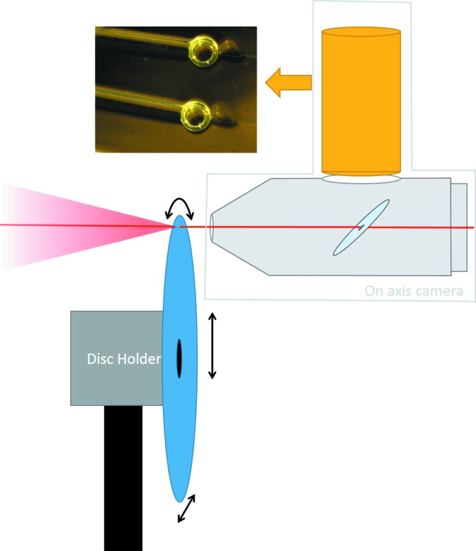
Figure 8.
Schematic diagram of the sample environment for the microfluidic disc. The disc (blue) is mounted on a motorized disc holder that can rotate the disc and translate it in vertical and horizontal directions for fine alignment. In the on-axis microscope, the camera (in yellow) points toward a mirror (light blue) inclined at 45° and provide images of the disc in the direction of the beam, without parallax error. A hole was drilled through the mirror to let the X-ray beam (red) go through, and the mirror is installed in vacuum to reduce air absorption and scattering.

