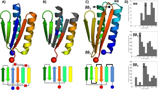
Figure 7.

Topology remodeling using MASTER. All structures are colored blue-to-red in the N-to-C terminal direction. (A) PDB entry 2KL8 along with its topology (below). Crossed out connections in the topology correspond to loops marked for deletion. (B) The structure with loops removed. Gray areas designate segments that are used for finding connector regions to bridge gaps in the new topology. (C) Remodeled structure with its topology shown underneath. Blue and red spheres designate N- and C-termini, respectively. (D) Histograms of connector lengths among close matches corresponding to each of the three regions to be bridged. The most likely length, marked with an asterisk for each connector, was chosen to produce the remodeled structure (see Materials and Methods section).
