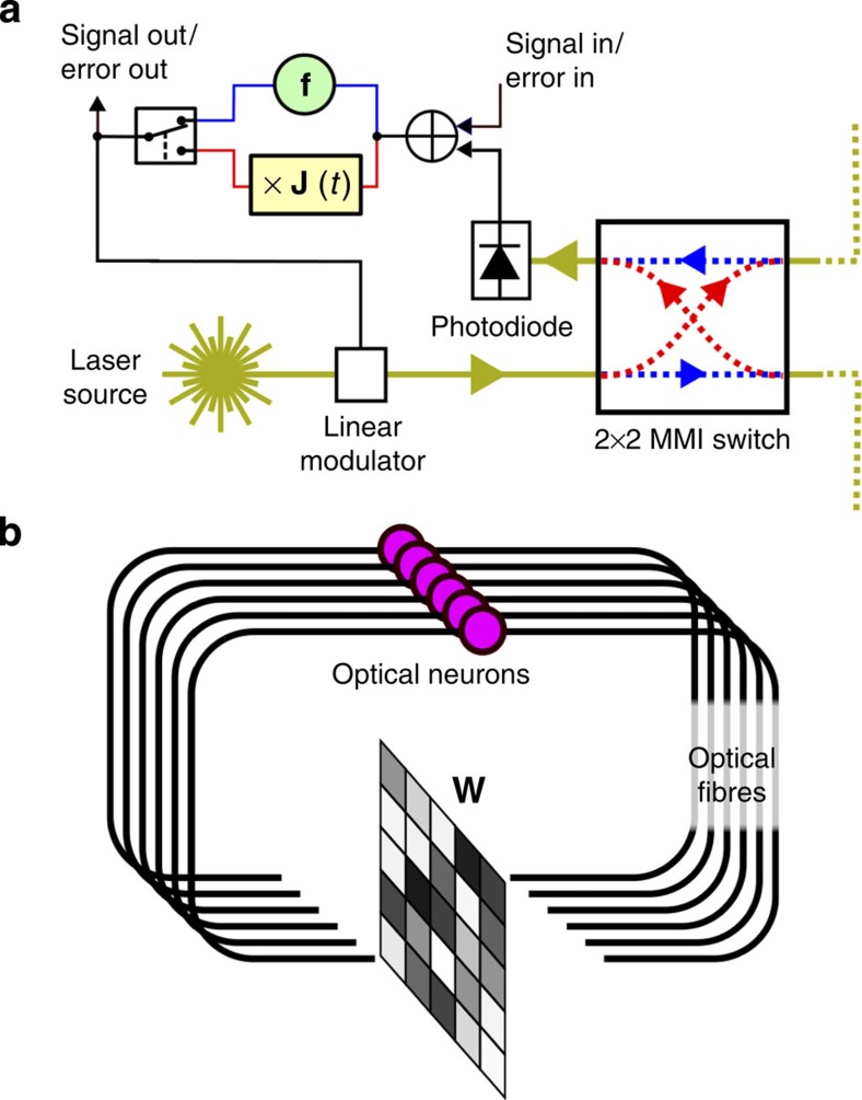
Figure 3. The electro-optical set-up.
(a) Schematic depiction of an electro-optical neuron, where pathways that are exclusive in the forward or backward mode are depicted in blue or red, respectively. It is largely similar to the electronic circuit in the acoustic set-up, with the difference that the input now enters the system before the nonlinearity. The 2 × 2 switch allows light to travel either forwards or backwards through the fibre network (fibres depicted by yellow lines). (b) Depiction of a network of electro-optical neurons, each purple circle represents a neuron. They send their output signals through optical fibres (which also incorporate delay) to an optical matrix–vector multiplier which multiplies with a matrix W in the forward direction and WT in the backwards direction. The elements of W can be set electronically, and are adapted in each training iteration. Note that each neuron also has an incoming and outgoing connection to external hardware that sends input and records output (not depicted).

