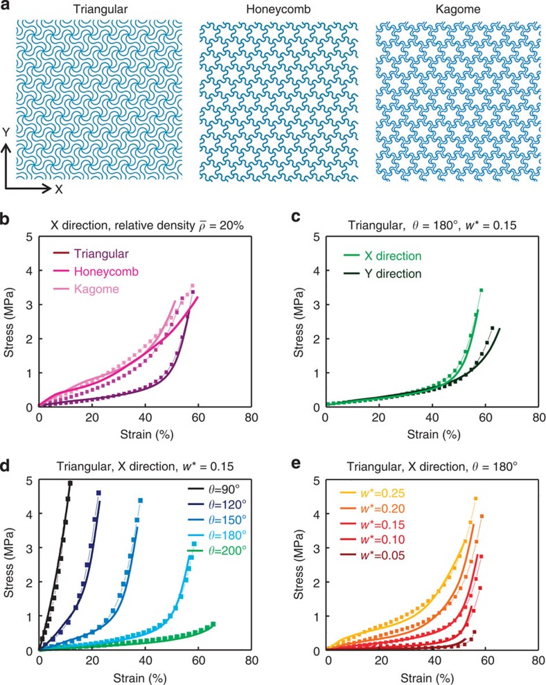
Figure 2. Wavy network architectures and design rules for tailored, non-linear stress–strain responses.
(a) Schematic illustrations of three different wavy network architectures, in which the node connection between the unit cells forms triangular (left), honeycomb (centre) and Kagome (right) lattices. Key parameters of these networks define the non-linear mechanical responses: lattice topology, direction of applied stress and arc angle (θ) and the normalized width (w*) of the horseshoe building blocks, as illustrated in frames b–e, respectively. In b–e, the experimental and FEA results are denoted by line, and line plus square symbol, respectively. The triangular lattice exhibits the most pronounced transition from low to high tangent modulus. Results of parametric studies of this type of mesh appear in d and e. The filament thicknesses are 55 μm in all cases.

