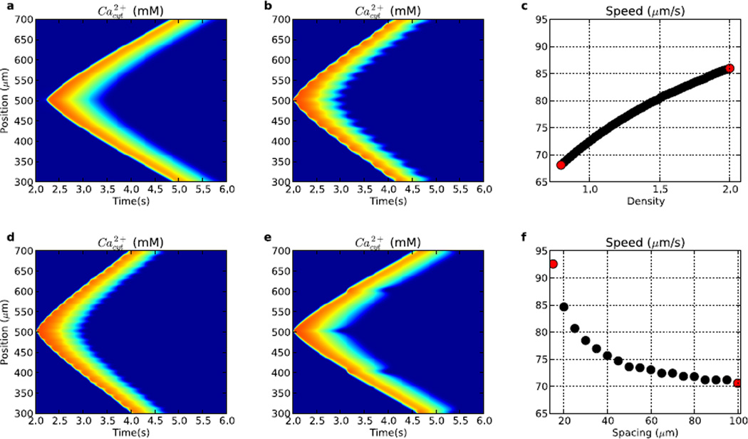
Figure 9.
Comparison of Ca2+ waves generated from varying ER stack properties. Simulations were run by varying density and spacing of ER stacks. ER density in between stacks was set at 0.8× baseline. (a) Ca2+ wave from 0.8× ER stack density with 20 µm spacing, (b) Ca2+ wave from 2.0× ER stack density with 20 µm spacing, (c) Ca2+ wave speed as a function of ER stack density (fixed 20 µm spacing), (d) Ca2+ wave from 15 µm ER stack spacing with ~1.87× density, (e) Ca2+ wave from 100 µm ER stack spacing with ~1.87× density, and (f) wave speed as a function of ER stack spacing. Note the bumps in Ca2+ release around ER stacks. (Colorscale in a,b,d,e same as in Fig. 2.) Red points in (c) ((f)) are from waves in (a),(b) ((d),(e)).

