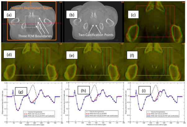
Figure 8.
(a) Reference image with three bounding boxes marked; (b) moving image; (c) reference (red) and moving (green) images overlaid before registration; (d) reference image (red) and moving image (green) overlaid after the B-spline-based VelocityAI registration; (e) and (f) reference image (red) and moving image (green) overlaid after registration with the FEM-DVFsmall and FEM-DVFlarge, respectively; The profiles of the B-spline-based DVF, FEM DVF and calcification point-enhanced FEM DVF along the red horizontal line marked in (a) were illustrated in (g), (h) and (i) which correspond to the small, middle and large bounding boxes, respectively.

