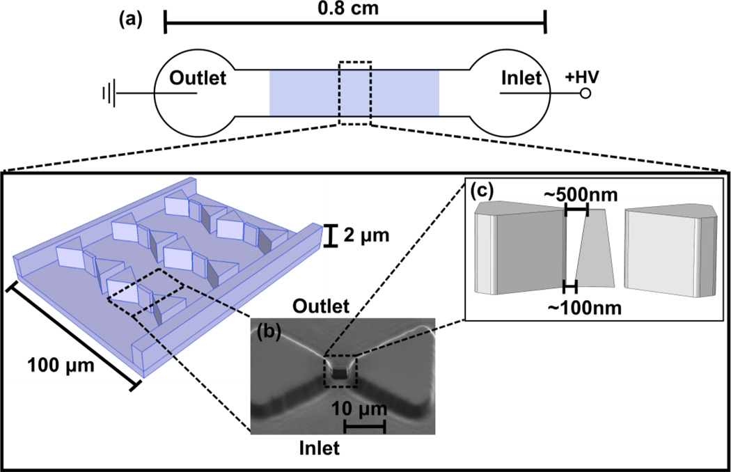
Figure 1.
Schematic of the iDEP device set-up (not to scale). a) A potential difference is applied to a microchannel exhibiting an insulator post array. b) Nanoconstrictions are created between the tips of triangular microposts by FIBM to achieve high electric field gradients for manipulation of nm-sized proteins. The location of these posts may vary up to 200 nm in between the tips of the larger triangular posts due to instrument limitations in positioning the focused ion beam. c) A scanning electron microscopy image of the triangular post with nanoconstrictions in the PDMS mold is also shown. d) A schematics illustrating the vertical positioning of the nanopost in between the microposts and the variations of distance to the microposts due to FIBM.

