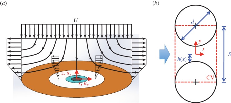
Figure 3.

Modelling flow through eyelashes. (a) Streamlines in the r−z plane associated with potential stagnation point flow with a linear boundary layer. (b) Geometry used in viscous flow analysis to determine an expression for the pressure drop ΔP across an array of eyelashes. The control volume is defined by the dashed rectangle, and the incoming airflow (arrow) flows through the gap between cylindrical lashes with diameter d. The centre-to-centre distance between lashes is defined as S and is assumed to be S ≈ d, where d is the lash diameter. (Online version in colour.)
