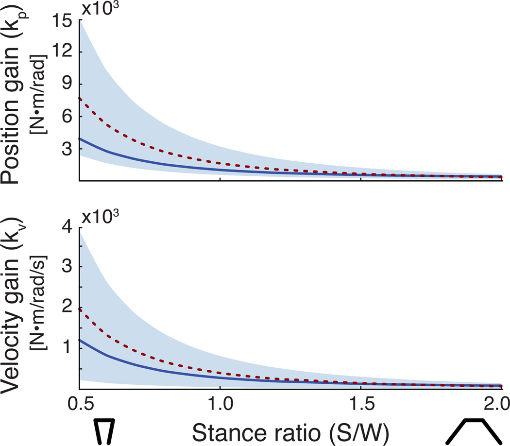
Figure 4.
Stable feedback gains across stance width. The shaded regions defined all stable feedback gains across stance widths. The dotted line indicates the feedback gain pairs that produced maximum stability radius across stance widths. The solid line indicates the feedback gain values that produced the same stability radius (r=0.8) across stance widths.

