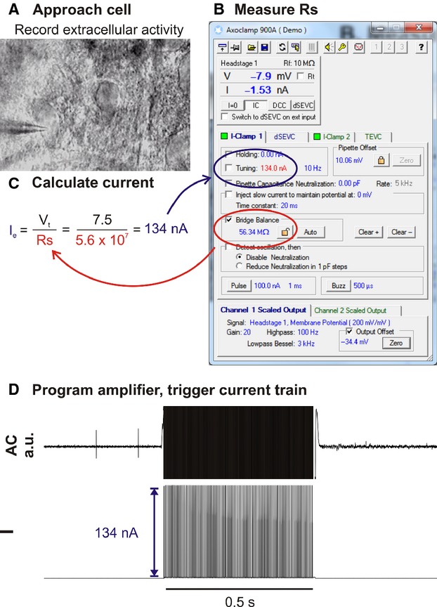
Figure 1.

Illustration of workflow used for constant‐current electroporation in vitro. (A) Recording pipette is moved into gentle contact with the target cell under optical guidance. (B) Immediately prior to electroporation Rs is measured using the amplifier bridge‐balance function and (C) used to calculate the electroporation current (Ie) required to generate the target voltage (Vt; in this example 7.5 V). (D) The amplifier is programmed to deliver a train of current pulses at Ie.
