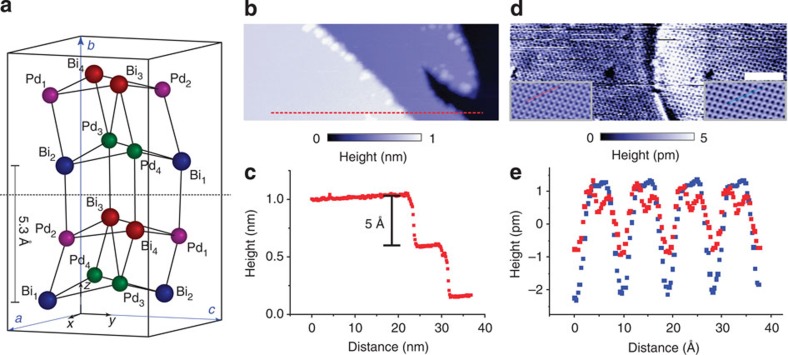
Figure 1. Crystal structure and topographic imaging.
(a) Crystal structure of BiPd. The dashed horizontal line indicates the preferred cleavage plane between layers of Bi atoms, equivalent planes are at the top and the bottom of the unit cell. Because BiPd is not centrosymmetric, the bottom and top surfaces of a cleaved crystal are not identical. (b) STM topography showing atomically flat terraces with step edges, (c) height profile extracted at the position indicated by a red dashed line in b, showing step edges with ≈5.3 Å height. The step height corresponds to half the height of the unit cell. (d) Topographic image of a twin boundary between the two different terminations of the crystal, showing atomic resolution on both of them. The insets show unit-cell averaged close-ups of the atomic corrugation on the two sides—both recorded with the same tip (scale bar, 5 nm). (e) Line cut along the lines indicated in panel d. From the two line cuts, it can be noted that the difference in height of the two Bi atoms is larger for the surface to the left of the boundary, whereas the modulation of the distance between the Bi atoms is larger for the corrugation on the right. This can be compared with the modulation of the height and interatomic distances expected from the crystal structure and yields an assignment of the left surface to a (010) termination and for the right surface to a  termination.

