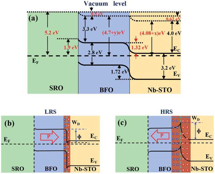
Figure 6. Schematic energy band for the conducting mechanism.
(a) Energy band diagram for the whole SRO/BFO/Nb-STO heterojunction; (b, c) present the schematic band diagrams for a p-n junction at two different ferroelectric polarization directions, with downward polarization state (b) and upward polarization state (c), corresponding to the LRS and HRS, respectively.

