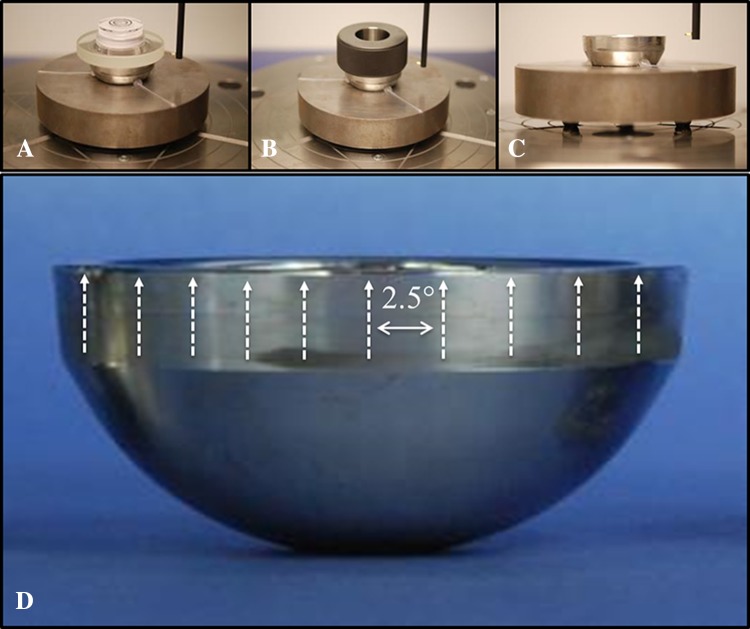
Fig. 1A–D.
The alignment procedure used in this study progressed from: (A) manual alignment to the (B) auto center and level of a ring gauge to (C) creation of a part datum from circumferential profiles. (D) This is a representation of the direction of the axial traces and their spacing about the circumference of the taper (not to scale).

