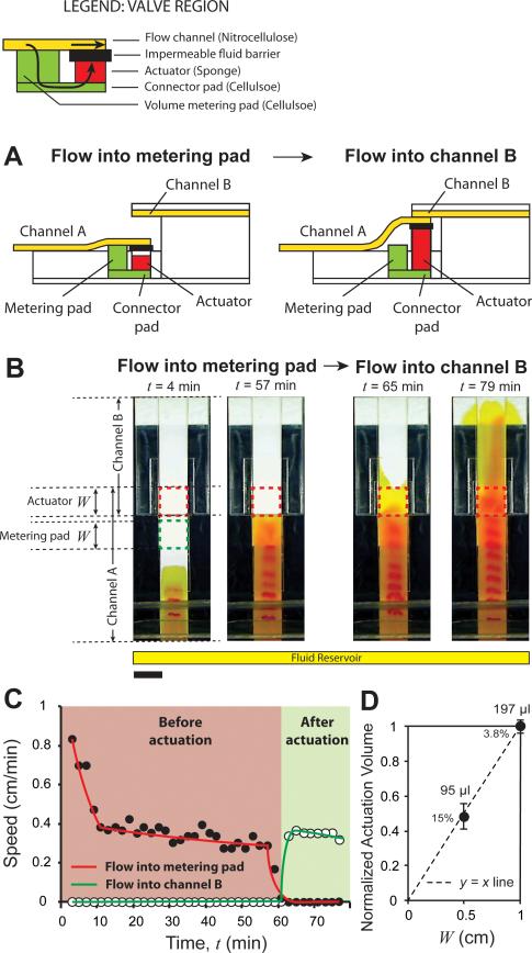
Figure 4.
Volume-metered valve with a cantilever channel. A. Schematic of a volume-metered flow-diversion switch. It consists of two channels, A and B, placed at two different heights. Channel A connects to a metering pad placed under it, which delivers fluid to an actuator, through a connector pad. After the passage of a certain volume of fluid, the actuator expands, disconnects channel A from the metering pad and connects it to channel B. B. Time-lapse images of the valve. The length of the metering pad and actuator, W, was 1 cm for this design. Before actuation (4 and 57 min), fluid in channel A flowed into the metering pad. After actuation (65 and 79 min), fluid was diverted into channel B. Scale bar is 1 cm. C. Linear velocity as a function of time for the device shown in B showed a steady flow into the metering pad (solid circles; red line) before actuation. During actuation, the velocity into the metering pad decreased to zero, and after actuation, velocity into channel B (hollow circles; green line) increased from zero to a positive value. D. Normalized mean volumes of fluid flow before valves actuated, as a function of W. Percent values are coefficients of variation. Mean volumes of actuation are provided next to the data points (N = 5 for W = 1 cm and N = 4 for W = 0.5 cm). In C, curves are added to guide the eye.

