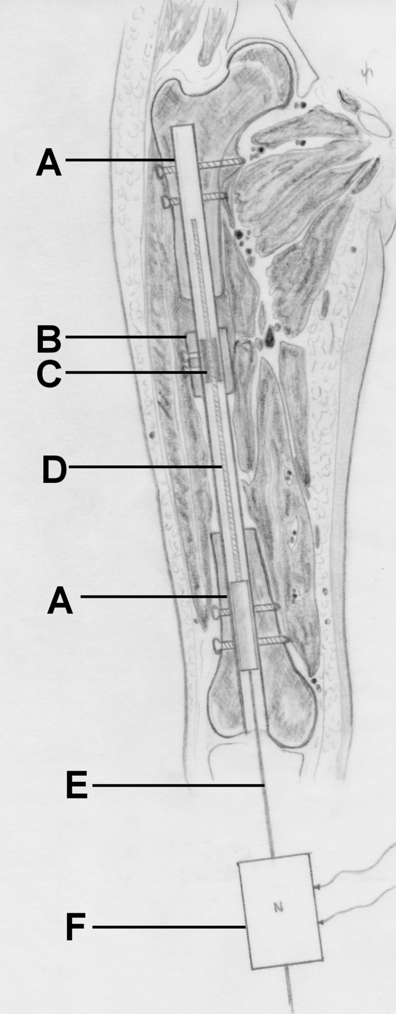
Fig. 4.

Schematic of the CDS implanted into the femur. A nail, B bone segment, C threaded rod spindle, D threaded rod, E traction wire, F load cell. By pulling on the load cell connected to the distal wire, bone segment transport is conducted and the required traction force can be measured simultaneously
