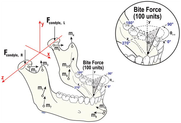
Fig. 3.
Craniomandibular geometry used in numerical modeling of jaw loading - The axis system and force vectors involved are illustrated for biting at right canine. The force vectors based on individual subjects’ anatomy included: TMJs (Fcondyle; R=right, L=left), and muscles representing five muscle pairs (m1,2=masseter, m3,4=anterior temporalis, m5,6=lateral pterygoid, m7,8=medial pterygoid, m9,10=anterior digastric muscles). Bite forces were modeled to mimic in vivo biting conditions, characterized by angles in the occlusal plane (θxz, 0–350°, illustrated above occlusal plane, and relative to vertical (θy, 0–40° shown as shaded, where 0° is normal to the occlusal plane). All TMJ and muscle forces required for static equilibrium were expressed relative to the 100-unit applied bite force.

