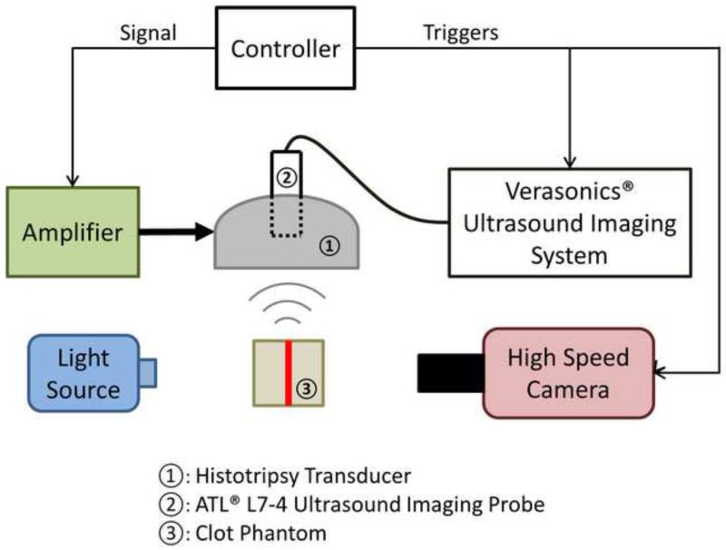
Figure 2.
A schematic illustration of the experimental setup. A 6-element 1.5-MHz histotripsy transducer was placed facing down in a water tank filled with degassed water. The transducer was driven by a high-voltage amplifier that was connected to a field-programmable gated-array (FPGA) development board specifically programmed for controlling the firing of the transducer. A 5-MHz ultrasound imaging probe was inserted in the central hole of the histotripsy transducer and connected to Verasonics® ultrasound imaging system to image at the transducer focus. A high-speed camera and a continuous-wave light source were placed on the two sides outside the water tank. The FPGA controller sent triggers to the Verasonics® system and the high-speed camera to synchronize them with therapy pulses. The therapy focus was positioned within the transparent fibrin clot phantom. The central plane of the clot plate, the ultrasound imaging plane and the focal plane of the camera were aligned to overlap with each other.

