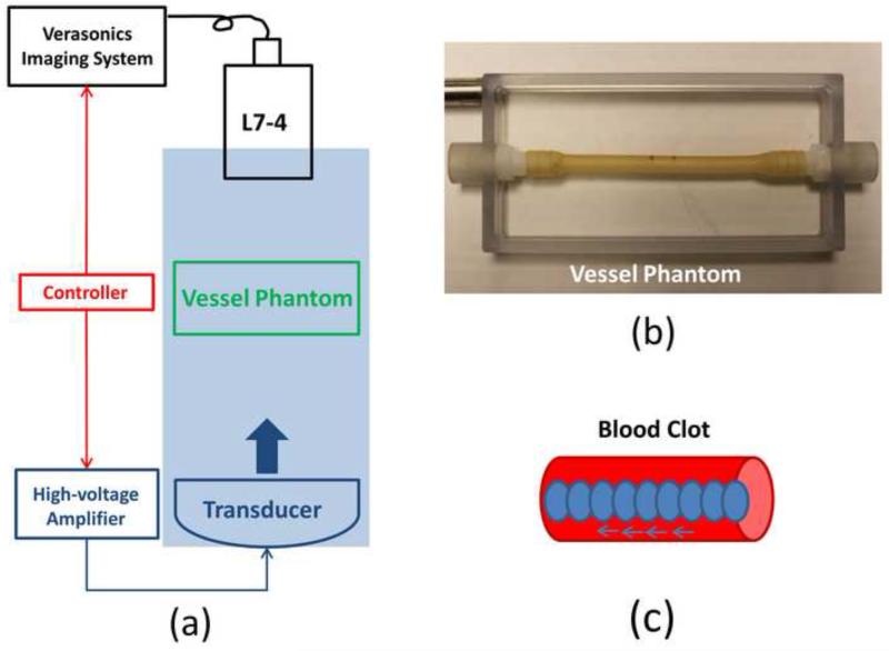
Figure 8.
(a) A schematic illustration of the in vitro experiment setup. An 18-element 1.25-MHz histotripsy transducer was placed facing up in a tank filled with the degassed water. The transducer was driven by a high-voltage amplifier which was connected by an FPGA controller. A 5-MHz ultrasound imaging probe was positioned opposite to the transducer, aligned rigidly to the treatment focus and connected to the Verasonics® ultrasound imaging system. The FPGA controller sent triggers to the Verasonics® system to synchronize them with therapy pulses. Vessel phantom was placed between the transducer and the ultrasound imaging probe. (b) A picture of the vessel phantom. (c) Strategy of recanalization treatment. Each ellipse represents a treatment focal spot and after the completion of each spot treatment, the focus will move to the adjacent location with a 0.7 mm separation.

