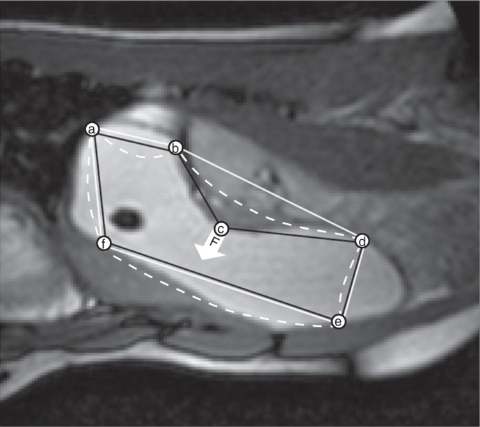
Fig. 3.

Magnetic linking procedure for ordering seed points (a to f) to form a polygon that approximates the edge of the ROI. A convex hull (17) polygon (a–b–d–e–f) is fitted through the seed points (solid white line). Because of concavities a few seed points (e.g., point c) do not form part of the convex hull as shown by the point c that is not at a vertex of the white convex hull polygon. The intensity gradient of the image at this “out-of-position” seed point is used as a “magnetic force” (F) on the sides of the convex polygon which attracts or repels the sides (white dashed lines). Whichever side first arrives at the out-of-position seed point is divided into two parts by including this seed point as a vertex leading to an appropriately ordered (a–b–c–d–e–f) concave polygon of seed points (black line). The process continues until all seed points are part of the polygon that approximates the edge of the ROI.
