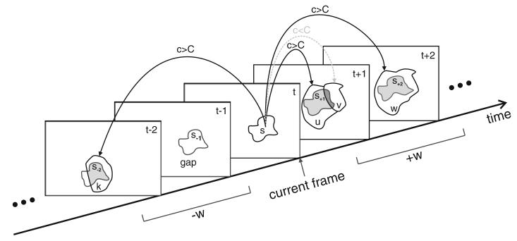
Figure 10. The process of trace intersection.
The trace of segment s is intersected with the segments k, u, v, and w in the neighboring frames. Gray regions represent the area of intersection with the trace. A temporal relationship (link) is established if the confidence c is higher than a threshold C. The trace intersection handles cases of splitting and merging as well as gaps in the temporal succession of segments.

