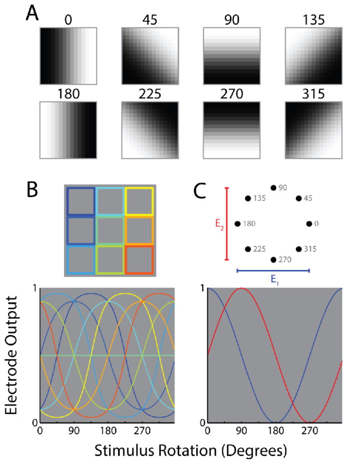
Figure 5.
A new quadrature code for vision. A. Eight rotations of a contrast edge symbolizing an image fragment from an external stimulus. B. The default, “pixel-to-electrode” code. In this example the image fragments in A are downsampled into a 3 pixel by 3 pixel representation. The intensity of each pixel maps onto a distinct electrode. Top, the portion of each image fragment that feeds into each pixel/electrode. Bottom, the corresponding electrode outputs over the full range of stimulus rotations. C. A hypothetical, “non-natural” code. This code calculates the dominant orientation and sign of the stimulus and represents this information using 2 electrodes. The first electrode transmits a signal proportional to the cosine of the calculated rotation and the second transmits a signal proportional to its sine; such signals are said to be in quadrature, as they are out of phase by 90 degrees. Top, the “coordinates” of the 2 electrode outputs at each of the rotations shown in A. Bottom, the corresponding electrode output over the full range of stimulus rotations.

