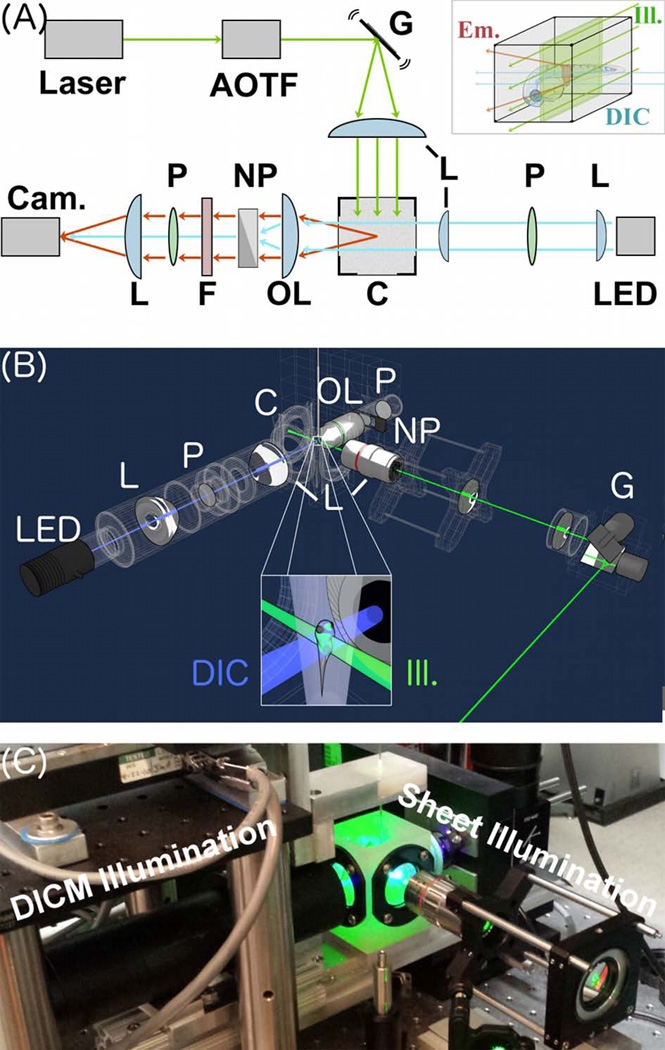
Figure 1.
A Combined Light Sheet Fluorescence and Differential Interference Contrast Microscope. (A) Schematic. Laser excitation light (green) is filtered with an acousto-optic tunable filter (AOTF) and formed into a sheet using a galvanometer-scanned mirror, G. The sheet plane is perpendicular to plane of the page. Fluorescence emission light is indicated in red. Transmitted light for DICM is indicated in blue. LED = light emitting diode for DICM illumination. P = polarizers; NP = Nomarski prism L = lenses; OL = objective lens; C = specimen chamber; F = filter wheel; Cam. = Camera. As described in the text, the right-side Nomarski prism is optional. Inset: the specimen chamber, highlighting a larval zebrafish specimen, the excitation light sheet, and the DICM light source. (B) A three-dimensional schematic rendering, with the same abbreviations and inset features as in (A). (C) A photograph of the setup.

