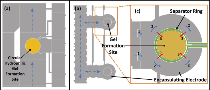
FIG. 3.
(a) Device A: Magnified section of EWOD layout used for hydrogel formation by using hydrophilic patterned sites (yellow circle) for gel formation. Blue lines show pathways for liquid delivery (calcium chloride, culture media, etc.) to the gel. (b) Device B: shows a magnified section of the EWOD mask design used for the encapsulation design. Blue dotted arrows show the pathways for fluid transport on 1.9 mm × 1.9 mm electrodes. Inset magnified image (c) shows the separator ring electrode (in green) that allows for on demand merging of the calcium chloride with sodium alginate. Blue arrows with numbers show how calcium chloride enters the encapsulating electrode (1) and then encapsulate the gel formation site (2). Actuation of the separator ring electrode causes calcium chloride to flow into and merge with the sodium alginate at the gel formation site as shown by red arrows (3). (b) and (c) Reprinted with permission from S. M. George and H. Moon, in 28th IEEE International Conference on Micro Electro Mechanical Systems (IEEE, 2015), pp. 443–446. Copyright 2015 IEEE.

