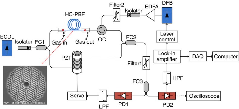
Figure 2. Experimental set-up for gas detection with 10-m-long HC-PBF.
The splitting ratios of FC1 and FC2 are, respectively, 80/20 and 50/50, which approximately balanced the powers in the two arms of the interferometer. The optical path lengths of the two arms are also balanced to minimize the laser phase to intensity noise conversation. Filter 1 is used to filter out the residual pump and Filter 2 to minimize the effect of EDFA's ASE noise. The splitting ratio of FC3 is 90/10. Output from PD1 passes a low-pass-filter (LPF) and is used for interferometer stabilization. Output from PD2 contains the PT-induced phase modulation signal. The driving current of the DFB is modulated at 50 kHz by use of the internal signal generator of the lock-in. Inset: scanning electron microscopy (SEM) image of the HC-1550-02 fibre's cross-section. DAQ, data acquisition; DFB, distributed feedback laser (the pump); ECDL, external-cavity diode laser (the probe); EDFA, erbium-doped fibre amplifier; FC1-FC3, fibre couplers; OC, optical circulator; PD1-PD2, photo-detectors; PZT, piezoelectric transducer.

