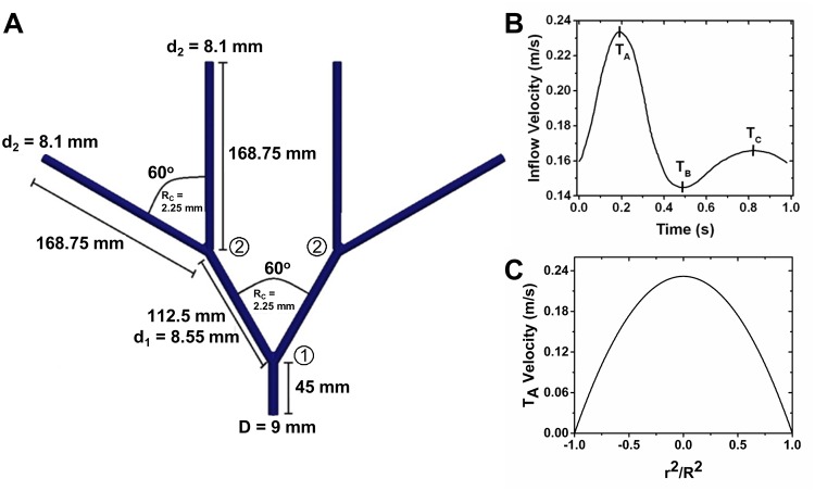
Fig 3. 3-Dimensional Idealized Femoral Artery Tree and Inflow Conditions.
(A) Dimensions of the idealized femoral artery tree. The bifurcations are defined by the circled numbers, with the first bifurcation defined as the 9 mm artery bifurcating into 8.55 mm arteries and the second bifurcation defined as an 8.55 mm artery bifurcating into 8.1 mm arteries. In both bifurcations, centerline to centerline of the daughter arteries = 60° and the Rc = 2.25 mm. Dimensions for only one side of the idealized femoral artery tree are shown due to symmetry. (B) The inflow velocity waveform applied at the geometric center of the parent artery. Marked peaks on the inflow velocity waveform are time points where comparisons of the two models are drawn. (C) Example inlet boundary condition across the parent artery at TA. X-axis is shown as squared distance from the vessel center (r) over the squared vessel radius (R). The origin (0,0,0) of the idealized femoral artery tree is defined as the geometric center of the parent artery, and all spatial locations given for this geometry are based on this origin in Cartesian coordinates.

