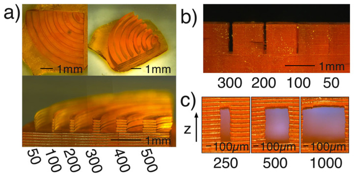
Figure 1. Images in (a) show a plan, isometric and end elevation view, of a characterisation structure.

The structure consists of concentric curved wall so that we can observe the x and y lateral resolution. The walls have different thicknesses as indicated (all values in µm) and are separated by 500µm. The layer thickness is 100µm. In (b) we measure the narrowest channels we can print. The structure has a depth of 5mm, and layer thickness of 100µm. The 50µm channel is blocked, the 100µm channel is partially open, the 200 µm is mostly clear, while the 300µm channel is fully open. In (c) we examine the capability of the printer at printing horizontal overhanging structures, which is important when designing fluid channels.
