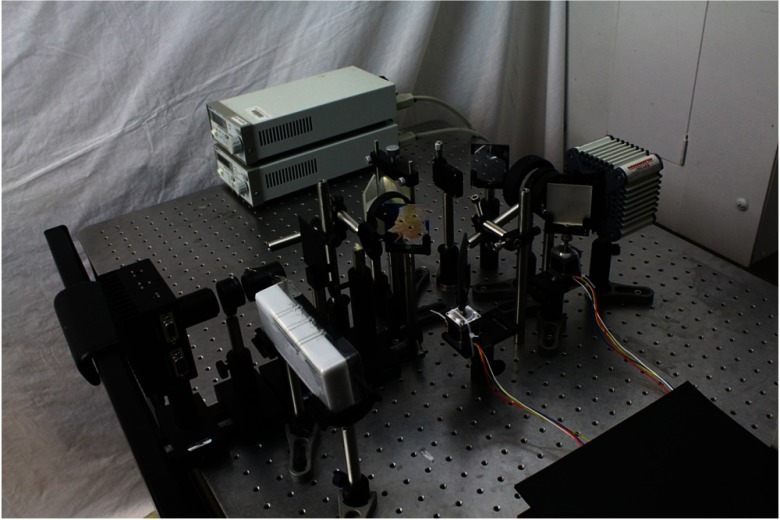
Fig. 4.
Photograph of the MDSI setup. As shown in the schematics in Fig. 2, a source shines a collimated beam through a dichroic mirror and a scanning mirror. An image of the phantom is formed at the mask plan and a secondary image for the masked phantoms reformed on the CCD sensor.

