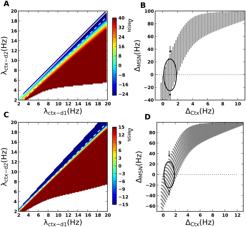
Fig 2. Balance of D1 and D2 MSNs firing rates as a function of cortical input rates.
(A) ΔMSN as a function of λctx_d1 and λctx_d2 (cf. Eq 1), scenario-I. Diagonal (marked with white line) represents the case that the two MSN populations receive equal cortical drive (λctx_d1 = λctx_d2, X = 0.0). With these inputs, ΔMSN is always negative. This shows the inherent bias towards D2, due to the asymmetrical connectivity. The area below the diagonal represents the regime of higher input drive to D1 λctx_d1 > λctx_d2, X > 0. Off-diagonal bands represent ΔMSN for a constant difference in cortical input rates (ΔCTX) to the two MSN populations. The dashed line marks the desirable regime of operation for the striatum, in which a systematic increase in the cortical input can reverse the sign of ΔMSN. (B) ΔMSN as a function of ΔCTX to the two MSN populations. For a constant value of ΔCTX, ΔMSN changes depending on λCTX (cf. Eq 1). The oval marks the region where an increase in the cortical input rates for a constant ΔCTX changes the sign of ΔMSN from positive to negative, indicating a higher firing rate of the D2 MSNs. (C) Same as in panel A for the scenario-II (cf. Eq 9). In this scenario we considered J C1 > J C2, therefore, the difference in the drive to D1 and D2 MSNs scales with the difference between J C1 and J C2. Since J C1 > J C2, the diagonal itself lies in a desirable regime, where ΔMSN changes from positive to negative for increasing cortical input rate. (D) Same as in panel B for the scenario-II.

