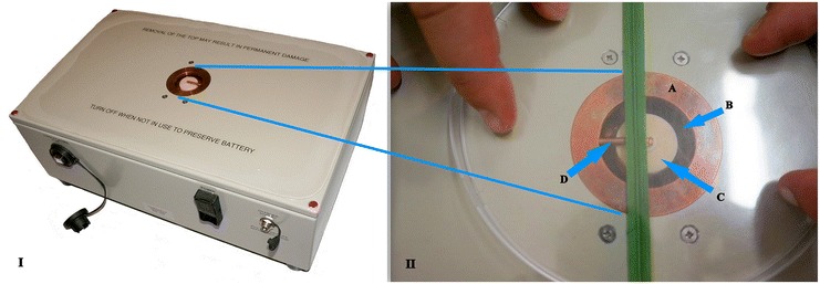
Figure 1.

Microwave sensor. (I) – Photograph of the employed sensor system comprising a compact battery - powered circuit board - microwave electronic module, and (II) the zoomed measurement-window: dual mode cavity (copper, A) embedded in a housing with a wheat leaf in measurement position. The aperture in the copper cavity (dark circle, B) allows the evanescent field of the ceramic dielectric resonator (smaller light circle, C) to penetrate into the sample under test. The radial copper rod (D) which is partially covered by the leaf is a requirement for Mode 0 only.
