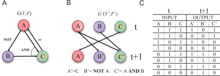
Fig. (4).
An example of Boolean network. (A) A Boolean network G(V,F). (B) The corresponding wiring graph of G(V,F) (C) The logic operations and state transition table. The possible input at time point and the corresponding output at time t+1 are listed in the table. Boolean network models the regulatory relationships in the logical operating scheme [106].

