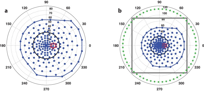
Figure 1.
The binocularly symmetric 164-point grid pattern used in all static perimetry exams in this study, shown in angular coordinates for the right-eye. (a) The test points and convex hull footprint are in blue, the blind spot search region is outlined in red, and the 30° central circle is black. (b) A wider view showing the zero-sensitivity boundary constraints in green and the gray outline of the interpolation grid used for surface modeling.

