Abstract
Multicellular spheroids are an important 3-dimensional cell culture model that reflects many key aspects of in vivo microenvironments. This paper presents a scalable, self-assembly based approach for fabricating microcavity substrates for multicellular spheroid cell culture. Hydrophobic glass microbeads were self-assembled into a tightly packed monolayer through the combined actions of surface tension, gravity, and lateral capillary forces at the water-air interface of a polymer solution. The packed bead monolayer was subsequently embedded in the dried polymer layer. The surface was used as a template for replicating microcavity substrates with perfect spherical shapes. We demonstrated the use of the substrate in monitoring the formation process of tumor spheroids, a proof-of-concept scale-up fabrication procedure into standard microplate formats, and its application in testing cancer drug responses in the context of bone marrow stromal cells. The presented technique offers a simple and effective way of forming high-density uniformlysized spheroids without microfabrication equipment for biological and drug screening applications.
Keywords: Self-Assembly, Multicellular Spheroid, Microbead-Microcavity, 3-Dimensional Cell Culture, Drug Screening
1 Introduction
Multicellular spheroids are a useful 3-dimensional cell culture model that can better mimic in vivo microenvironments than 2D cultures (Pampaloni et al. 2007). Microspheroids have been widely applied in stem cell biology (Bartosh et al. 2010; Subramanian et al. 2014), tissue engineering (Kelm and Fussenegger 2004), tumor biology (Hirschhaeuser et al. 2010), and drug screening (Friedrich et al. 2009). The goal of this work was to develop a simple, tunable cell culture platform that allows for easy and reliable formation of multicellular spheroids without need for sophisticated equipment to help broaden adoption to biological laboratories.
The assembly of multicellular spheroids takes advantage of cell-cell adhesion in the absence of cell attachment to substrate, which leads to spontaneous aggregation of cells into spherical micro-tissues. Conventional spheroid culture methods include spinner suspension culture (Sutherland et al. 1971), agar plate static culture (Yuhas et al. 1977), centrifugation pellet culture (Johnstone et al. 1998), and hanging drops (Kelm et al. 2003). These approaches, however, can impose high shear stress on the cells, generate heterogeneous spheroid sizes and geometries, or have limited throughput restricting the scale of read-out and statistical power of experimental analyses. Recently, microtechnologies including microfabrication (Karp et al. 2007; Klo et al. 2008; Ungrin et al. 2008; Park et al. 2009), micropatterning (Khademhosseini et al. 2006; Tamura et al. 2008; Hardelauf et al. 2011), microfluidics (Torisawa et al. 2007; Jin et al. 2011; Kim et al. 2012), and 3-dimensional prototyping (Napolitano et al. 2007) have been employed in producing microwell substrates that are capable of producing large amounts of homogeneously-sized multicellular spheroids. Throughput remains a considerable issue; these methods typically involve extended processes with slow turn-around in changing design parameters. They also demand highly-specialized equipments which are largely inaccessible to most biological laboratories. In addition, these spheroid cell culture substrates usually have significantly different form-factor than traditional microplates, thus limiting their ability to integrate with conventional microplate-based high-throughput platforms.
Self-assembly is a process that happens on many levels in nature (Philp and Stoddart 1996; Fernandez and Khademhosseini 2010) and is capable of forming highly organized structure without external energy input. At nanometer scales, colloidal particles can self-assemble into two-dimensional array at an air-liquid interface (Yamaki et al. 1995). This concept has been applied in self-assembling block copolymer micelles in monolayers for surface patterning in order to define nanometer-sized periodic arrangements of adhesion molecules (Glass et al. 2003; Arnold et al. 2004). At micrometer to millimeter scales, self-assembly guided by lateral capillary forces and hydrophilic-hydrophobic interactions, has been explored in forming 2-dimensional surface patterns and 3-dimensional structures (Bowden et al. 1997; Clark et al. 2001; Fernandez and Khademhosseini 2010). However, the use of self-assembly in defining surface topology has not been reported to date.
In this report, we developed a technique using self-assembly concepts to create a microcavity substrate for multicellular spheroid cell culture. It utilizes the combined actions of hydrophobicity, surface tension, gravity, and lateral capillary force to guide the formation of a microbead monolayer at the liquid-air interface. The technique is advantageous by: (1) creating a high density of microwells with uniform sizes compared to conventional techniques, (2) simplifying the synthesis of a spheroid culture substrate compared to microfabrication methods, and (3) integrating with standard microplates for high-throughput applications.
2 Experimental
2.1 Surface functionalization of glass beads
Glass beads of different diameters were purchased from Sigma (St. Louis, MO) and filtered through brass sieves to obtain high uniformity. The beads were cleaned for 30 min in 3:1 volume mixture of 30 % ammonium hydroxide and 30 % hydrogen peroxide heated to 60 °C in a fume hood, then rinsed thoroughly in deionized water, and serially replaced three times by 100 % ethanol. The beads were then functionalized with Silanization Solution I (5 % dichlorodimethylsilane in heptane, Sigma), before being rinsed three times with 100 % ethanol and air-dried in the fume hood.
2.2 Microbead monolayer formation on a polymer base and replication of microcavity substrate
Polyvinyl alcohol (PVA) (Sigma) was dissolved as 5 % (w/v) solution in de-ionized water, and 2~5 mL of the solution was transferred into a 35 mm petri dish. Silanized glass beads were then gradually dropped onto the meniscus from the edge of the dish, which floated on the liquid-air interface due to hydrophobicity, and spontaneously accumulated into a single, closely packed layer at the center of the meniscus by lateral capillary forces. Once the bead layer reached desired coverage (2~3 cm in diameter), the PVA solution was allowed to air-dry for 24–48 h into a solid sheet in which a monolayer of packed glass bead was tightly embedded. The bead-embedded PVA film was used as a master template for subsequent replication of microcavity substrates in polydimethylsiloxane (PDMS). Briefly, Sylgard® 184 base polymer was mixed 10:1 with curing agent, mixed thoroughly and poured onto bead-embedded PVA film. After curing at 75 °C in oven, the PDMS layer was peeled off and trimmed into desired sizes for different petridish/microplate sizes. Prior to cell culture, all PDMS microcavity substrates were coated with 0.2 % w/v Pluronic F127 (Sigma) and rinsed three times with PBS.
2.3 Cell culture
Breast cancer cell line MDA-MB-231 was purchased from ATCC; HMLER cells were a generous gift from Weinberg lab (Ince et al. 2007). HMLER cells were engineered to express firefly luciferase with a lentivirus containing luciferase reporter following a previous report (Love et al. 2007). MDA-MB-231 cells were cultured in Dulbecco’s MEM (DMEM) supplemented with 10 % FBS, 100 U/ml penicillin and 100 μg/ml streptomycin. HMLER cells were grown in Mammary Epithelial Growth Medium (MEGM) (Lonza). Bone-marrow mesenchymal stromal cells (BMSCs) were derived from whole human bone marrow aspirates (Lonza) (Parekkadan et al. 2007), and maintained in alpha-modified Minimum Essential Medium Eagle (alpha-MEM), 20 mg/L gentamycin, 4 % FBS, 2.5 ug/L rhFGF-basic (R&D Systems), 100 U/ml penicillin, and 100 μg/ml streptomycin. For spheroid culture, cells were trypsinized and resuspended in 4×10⁵/ml and seeded in wells in 150 μL aliquots. 10 % Matrigel® (BD Biosciences) was added to MDA-MB-231 spheroid culture to promote spheroid formation (Ivascu and Kubbies 2006). Cell growth in microcavity substrates were monitored on Zeiss 200 M inverted microscope with environmental control (37 °C, 5 % CO2 and 95 % humidity).
2.4 Replication and scaling-up of microcavity substrates into microplates
PDMS double casting (Sniadecki and Chen 2007) was used for multiple rounds of replication of surface morphologies. Briefly, PDMS surfaces with desired geometric shapes molded from templates were treated for 5 min with oxygen plasma (Harrick, PDC-32G), and placed overnight in vacuum desiccator with a few drops of trichloro (1H,1H,2H,2H-perfluorooctyl) silane (Sigma). The treated PDMS surfaces were then used as template for replicating complementary shapes by a new round of PDMS curing. For molding microplate geometries, PDMS templates with protruding topologies were first trimmed in stripes with standard periodical width of 96-well microplate, stitched, and replicated onto a standard glass slide (1 in. by 3 in.). Plastic gaskets from Nunc™ LabTek™ chamber slides (Thermo Scientific) were pressed against double-casted microcavity surface on a glass slide for PDMS curing. Sylgard® 184 was used for the most PDMS casting in the replicating processes; Sylgard® 170 was used for the fabrication of black plates.
2.5 Drug treatment
Anti-cancer drugs Cisplatin and 5-Fluorouracil (5-FU) were obtained from Massachusetts General Hospital (MGH) Pharmacy. Drugs were applied onto spheroid cultures 24 h after initial cell seeding. The duration of drug treatment was 48 h for both drugs. At the end of the cell culture, half of the media were replaced with fresh media containing luciferin (150 μg/mL), and measured for luciferase activity by bioluminescent imaging indicated by the peak photon-flux emitted from individual wells, using Xenogen IVIS Imaging System 100 at MGH Center for Systems Biology.
3 Results and discussion
3.1 Fabrication of the microwell substrate
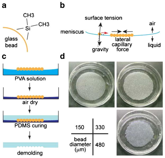
Microcavity wells were created by embedding a template of glass microbeads in polyvinyl alchohol (PVA) polymer. PVA immobilized the beads, which occupied a spherical space based on the natural bead structure. The PVA film also formed a basement surface and exposed only the top half of the spherical surfaces, allowing for easy de-molding of the replicating materials. Glass microbeads were silanized to acquire hydrophobicity (Boks et al. 2008) (Fig. 1a). PVA water solution was used to form an air-liquid interface to float the microbeads. With combined action of gravity and surface tension (Fig. 1b), the concave curvature of the air-liquid interface directed the accumulation, and with lateral capillary force (Kralchevsky and Nagayama 1994), led to the formation of a closely-packed (in hexagonal lattice) layer of floating beads at the center of the meniscus. When the PVA solution was air-dried (at room temperature, 25 °C), PVA formed a solid film and trapped the beads in their closely-packed formation. During the procedure, a steady evaporation environment of the underlying liquid was maintained by keeping the temperature constant and avoiding air turbulence, as the floating beads could be disturbed by the convections/microcirculations in the liquid or the air above the interface, particularly by heating or air circulation. The dried surface can then be used as a master template for replicating concave hemispherical shapes in polydimethylsiloxane (PDMS) (Fig. 1c). We tested bead diameters ranging from 150 μm to 500 μm, which all resulted in uniform monolayers of microbead template (Fig. 1d).
Fig. 1.
Fabrication of microbead templates by self-assembly. a Glass beads were treated with dimethyldichlorosilane to become hydrophobic. b Treated glass beads were deposited onto 5 % polyvinylalchohol (PVA) solution, and self-assembled into a monolayer by the combined act of gravity, surface tension, and lateral capillary force. c The PVA solution was air-dried and the glass beads were consequently embedded in the solidified PVA layer, which was then used as a template to form spherical cavities in the molding material (PDMS). d Images of glass bead templates of various diameters embedded in PVA film after drying (in 35 mm petri dishes)
3.2 Characterization of microbead template
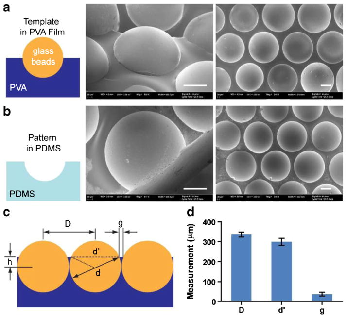
Scanning electron microscopy (SEM) of the glass-bead template and the replicated PDMS microwells was conducted to characterize the embedding of glass microbeads in the PVA film. The size and shape of the concave microwells are directly determined by those of the glass beads. As shown in the SEM images in Fig. 2a, a layer of 330 μm glass microbeads were embedded in a PVA layer, and the spherical shape was replicated into PDMS as shown in Fig. 2b. The center-to-center distance (D in Fig. 2c) of the microbeads were measured as 335 μm (standard deviation, SD=12 μm), while the exposed hemisphere were measured with average diameter of 298 μm (SD=18 μm). Assuming the diameter of the beads were precisely at 330 μm, the results suggest that the beads were tightly packed (with an average gap of 5 μm between the microbeads), and embedded “waist-up” by 71 μm (h in Fig. 2c) in the PVA layer. Such embedment left an apparent plateau of 36 μm (g in Fig 2c, with SD=10 μm) between the microwells (Fig. 2d).
Fig. 2.
SEM images of glass bead template and replicated PDMS wells, and size characterization. a Glass beads embedded in the PVA layer, with the top half exposed. b Replicated hemispherical microcavity in PDMS. Scale bars in (a) and (b): 100 μm. c Description of distance and size parameters for beads embedded in PVA film. d Measurement of the center-to-center distance D, exposed bead-cap diameter d′, and gap between bead caps g. Error bars: SD
3.3 Cancer spheroid formation on microcavity substrate and spheroid size control
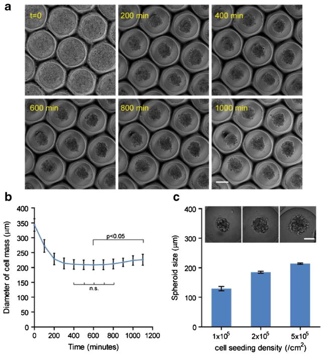
The application of microcavity substrates in directing multicellular spheroid formation was evaluated using MDA-MB-231 breast cancer cells. MDA cells were seeded on microcavity substrates molded from 500 μm diameter microbeads. The spheroid formation process was captured using real-time microscopy (Fig. 3a). Initially cells settled in the individual wells. Since the PDMS wells had been treated by Pluronic F127 to become non-adhesive, cells attached to each other and self-assembled into spheroids within 5 h, as indicated by decreasing lateral dimension of the cell aggregates (Fig. 2b). The size of the spheroids was constant within the next 5 h and then gradually increased in diameter, suggesting resumed cell growth within the aggregates (1-way ANOVA, Fig. 3b). Notably, since each microcavity substrate contained a large number of hemispherical wells (with areal density of 1.15 wells/mm2 and up to ~560 wells per substrate for those molded from 500 μm microbeads), the biological behavior of spheroids can be monitored with high accuracy and statistical power. Another advantage of our microcavity wells is the natural spherical shape molded from the microbeads, which promote more spherical spheroid formation than flat bottom wells commonly seen in microfabricated substrates (Choi et al. 2010; Wong et al. 2011).
Fig. 3.
Cancer spheroid formation in the microcavity wells and spheroid size control. a MDA-MB-231 breast cancer spheroid formation process from initial cell seeding to spheroid formation; scale bar: 200 μm. b The diameter of cell area in the lateral direction over 16 h. Statistics: 1-way ANOVA; n.s.: not significant. Error bars: SD. c Multicellular spheroids of MDA-MB-231 cells with different diameters were formed by controlling areal seeding density of cells on a microcavity substrate replicated from 500 μm beads, and quantification of spheroid diameter in relation to the seeding density. Error bars: SD. Scale bar: 100 μm
The initial size of the spheroids can be controlled in two ways—the size of the microcavity by altering the diameter of the glass microbead in the template, or the cell seeding density. The latter offers greater flexibility as it does not involve alterations in the design parameters. As seen in Fig. 3c, seeding densities from 1, 2, to 5×10⁵/cm2 were tested on the microcavity substrate molded from 500 μm glass beads. The resultant spheroid size ranged from 129 μm, 185 μm, to 213 μm, respectively. Theoretically there is no lower limit for the spheroid size as the seeding density can get down to essentially one cell per well. On the other hand, the upper limit of the spheroid size is determined by the volume of a single microcavity, because cell-cell adhesion will no longer be limited within a single microcavity when it is overfilled. Assuming the microcavities are perfect hemispheres, and cells are fully packed in the hemisphere and do not change volume during aggregation, then:
Where d is the diameter of the microbead, and dmax is maximal spheroid size. Therefore:
Under these simplified assumptions, a maximum of 396 μm spheroid can be formed on a 500 μm microbead molded substrate. In reality, more parameters should be considered such as the position of the “waistline” as defined in Fig. 2c, and the intercellular space.
3.4 Scaling-up into multi-well plate
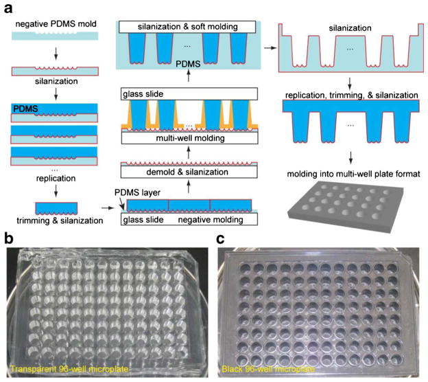
One of the limiting factors for most spheroid culture platforms is the capability to perform high-throughput studies (Napolitano et al. 2007). We aimed to scale up and adapt our microcavity substrate to conventional multi-well plates and thereby leverage existing high-throughput techniques (Major 1998; Battersby and Trau 2002). As a proof-of-concept, we employed multiple rounds of double casting (Sniadecki and Chen 2007) to fabricate the microcavity substrate into 96-well microplate format. As illustrated in Fig. 4a, spherical geometries were first replicated into PDMS templates, and then transferred onto a glass slide to form a large, continuous negative mold. One of the following key steps was to replicate the microbead geometry on top of large PDMS posts that later serve as molds for microplate wells. Plastic wells detached from Nunc™ LabTek™ 16-well chamber slide was used as mold for its identical well-to-well distance to the microplates and slope for the releasing of the template from molding surface. An additional round of double-molding yielded a large number of PDMS soft mold for producing final micro-plate products. PDMS was chosen for its good biological compatibility in cell culture applications (Sia and Whitesides 2003). Transparent Sylgard® 184 was selected for microscopy-related applications (Fig. 4b), and nontransparent Sylgard® 170 was used for luminescence-related applications (Fig. 4c). Each of the microwells contained 37 hemispherical microcavities (for 500 μm diameter microbeads), providing sufficient statistical power for downstream analysis.
Fig. 4.
Proof-of-concept scale-up process of microcavity template into microplates. a The procedure of scaling up the microcavity template into microplate format. With multiple rounds of double-casting (silanization plus two rounds of casting into complementary shapes), the spherical shape was transferred onto a PDMS post arrays with dimensions following standard microplates. Spherical microcavities were replicated into 96-well microplate in b transparent (Sylgard® 184) and c non-transparent (Sylgard® 170) PDMS
3.5 Drug treatment on tumor spheroids
The scaled microcavity microplate was applied in testing anti-cancer drugs on tumor spheroids. Bone marrow stromal cells (BMSCs) have been shown to affect tumor growth and drug sensitivity (McMillin et al. 2010). HMLER breast cancer cells engineered with firefly luciferase gene were plated with or without BMSCs and allowed to form spheroids overnight in a black microcavity microplate (molded in Sylgard® 170). Cisplatin and 5-Fluorouracil (5-FU) were subsequently added to cell culture in a series of concentrations. Tumor specific cell growths were then monitored by measuring luciferase activity with bioluminescence imaging (Fig. 5a). Luciferase activities under different conditions were normalized against the wells with neither drug treatment nor stromal cells. HMLER spheroids responded to Cisplatin treatment in a dose-dependent manner without or with BMSCs (Fig. 5b). The co-culture of BMSC with HMLER cells increased spheroid growth by 32.8 % (p<0.05). Interestingly, the co-culture with BMSC also reduced the half maximal inhibitory concentration IC50 of the HMLER cells to Cisplatin, from 19.1 μM to 16.7 μM, indicating a role of BMSC in sensitizing HMLER cells to the drug. On the contrary, HMLER cells were relatively insensitive to 5-FU treatment, with cell viability remaining above 50 % throughout the tested concentration range (0~100 μM), with or without BMSC. The platform developed here has significant advantage over conventional spheroid culture techniques when performing high-throughput studies. It increases spheroid number of the same condition by many folds without altering spheroid geometries, thus enhancing signal output and lowering the requirement for highly sensitive reading equipment. It also increases the statistical power by sheer number of the spheroids under the same condition without additional operations or wells.
Fig. 5.
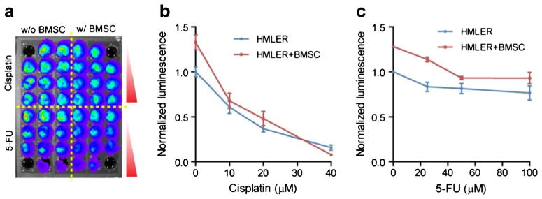
Drug treatment study with multi-well micro-hemisphere plate. a A black microcavity well plate was used for the formation of multicellular spheroid of HMLER breast cancer cells and/or BMSC for the measurement of drug dose response with bioluminescence assay. Measured response curve without or with stromal cells (BMSC) to b cisplatin and c 5-FU. Error bars: SD
4 Conclusion
In summary, we presented a self-assembly based method for fabricating microcavity wells for multicellular spheroid studies. The major advantage of our approach is that the material and method is easily accessible and simple in operations, and the self-assembly process completely eliminated the need for microfabrication equipments, making it suitable for engineering resource-limited research environments. The substrate can also be easily scaled up into microplate format and is thus compatible with standard microplate operations. The capability of the technology in creating large numbers uniform microcavities in a single well can significantly improve the statistical power of cell culture analysis compared to other non-microfabrication based single-spheroid culture techniques. This technology can find wide applications in 3-dimensional multicellular spheroid cultures for cancer and stem cell research, tissue engineering, and pharmaceutical discovery.
Acknowledgments
We thank Dr. Robert A. Weinberg for the HMLER cells, and Peter Waterman for assistance with in vitro bioluminescence imaging. This work was supported in part by National Institutes of Health Grants R01EB012521 (B.P.) and K01DK087770 (B.P.), and also by Massachusetts General Hospital Fund for Medical Discovery 2011A053483 (K.S.).
Contributor Information
Keyue Shen, Department of Surgery, Center for Engineering in Medicine and Surgical Services, Massachusetts General Hospital, Harvard Medical School and the Shriners Hospitals for Children, Boston, MA 02114, USA.
Jungwoo Lee, Department of Surgery, Center for Engineering in Medicine and Surgical Services, Massachusetts General Hospital, Harvard Medical School and the Shriners Hospitals for Children, Boston, MA 02114, USA.
Martin L. Yarmush, Department of Surgery, Center for Engineering in Medicine and Surgical Services, Massachusetts General Hospital, Harvard Medical School and the Shriners Hospitals for Children, Boston, MA 02114, USA. Department of Biomedical Engineering, Rutgers University, Piscataway, NJ 08854, USA
Biju Parekkadan, Email: biju_parekkadan@hms.harvard.edu, Department of Surgery, Center for Engineering in Medicine and Surgical Services, Massachusetts General Hospital, Harvard Medical School and the Shriners Hospitals for Children, Boston, MA 02114, USA. Harvard Stem Cell Institute, Cambridge, MA 02138, USA.
References
- Arnold M, Cavalcanti-Adam EA, Glass R, Blümmel J, Eck W, Kantlehner M, Kessler H, Spatz JP. Chem Phys Chem. 2004;5:383–388. doi: 10.1002/cphc.200301014. [DOI] [PubMed] [Google Scholar]
- Bartosh TJ, Ylostalo JH, Mohammadipoor A, Bazhanov N, Coble K, Claypool K, Lee RH, Choi H, Prockop DJ. Proc Natl Acad Sci U S A. 2010;107:13724–13729. doi: 10.1073/pnas.1008117107. [DOI] [PMC free article] [PubMed] [Google Scholar]
- Battersby BJ, Trau M. Trends Biotechnol. 2002;20:167–173. doi: 10.1016/s0167-7799(01)01898-4. [DOI] [PubMed] [Google Scholar]
- Boks NP, Norde W, van der Mei HC, Busscher HJ. Microbiology. 2008;154:3122–3133. doi: 10.1099/mic.0.2008/018622-0. [DOI] [PubMed] [Google Scholar]
- Bowden N, Terfort A, Carbeck J, Whitesides GM. Science. 1997;276:233–235. doi: 10.1126/science.276.5310.233. [DOI] [PubMed] [Google Scholar]
- Choi YY, Chung BG, Lee DH, Khademhosseini A, Kim JH, Lee SH. Biomaterials. 2010;31:4296–4303. doi: 10.1016/j.biomaterials.2010.01.115. [DOI] [PubMed] [Google Scholar]
- Clark TD, Tien J, Duffy DC, Paul KE, Whitesides GM. J Am Chem Soc. 2001;123:7677–7682. doi: 10.1021/ja010634l. [DOI] [PubMed] [Google Scholar]
- Fernandez JG, Khademhosseini A. Adv Mater. 2010;22:2538–2541. doi: 10.1002/adma.200903893. [DOI] [PMC free article] [PubMed] [Google Scholar]
- Friedrich J, Seidel C, Ebner R, Kunz-Schughart LA. Nat Protoc. 2009;4:309–324. doi: 10.1038/nprot.2008.226. [DOI] [PubMed] [Google Scholar]
- Glass R, Moller M, Spatz JP. Nanotechnology. 2003;14:1153–1160. [Google Scholar]
- Hardelauf H, Frimat JP, Stewart JD, Schormann W, Chiang YY, Lampen P, Franzke J, Hengstler JG, Cadenas C, Kunz-Schughart LA, West J. Lab Chip. 2011;11:419–428. doi: 10.1039/c0lc00089b. [DOI] [PubMed] [Google Scholar]
- Hirschhaeuser F, Menne H, Dittfeld C, West J, Mueller-Klieser W, Kunz-Schughart LA. J Biotechnol. 2010;148:3–15. doi: 10.1016/j.jbiotec.2010.01.012. [DOI] [PubMed] [Google Scholar]
- Ince TA, Richardson AL, Bell GW, Saitoh M, Godar S, Karnoub AE, Iglehart JD, Weinberg RA. Cancer Cell. 2007;12:160–170. doi: 10.1016/j.ccr.2007.06.013. [DOI] [PubMed] [Google Scholar]
- Ivascu A, Kubbies M. J Biomol Screen. 2006;11:922–932. doi: 10.1177/1087057106292763. [DOI] [PubMed] [Google Scholar]
- Jin HJ, Cho YH, Gu JM, Kim J, Oh YS. Lab Chip. 2011;11:115–119. doi: 10.1039/c0lc00134a. [DOI] [PubMed] [Google Scholar]
- Johnstone B, Hering TM, Caplan AI, Goldberg VM, Yoo JU. Exp Cell Res. 1998;238:265–272. doi: 10.1006/excr.1997.3858. [DOI] [PubMed] [Google Scholar]
- Karp JM, Yeh J, Eng G, Fukuda J, Blumling J, Suh KY, Cheng J, Mahdavi A, Borenstein J, Langer R, Khademhosseini A. Lab Chip. 2007;7:786–794. doi: 10.1039/b705085m. [DOI] [PubMed] [Google Scholar]
- Kelm JM, Fussenegger M. Trends Biotechnol. 2004;22:195–202. doi: 10.1016/j.tibtech.2004.02.002. [DOI] [PubMed] [Google Scholar]
- Kelm JM, Timmins NE, Brown CJ, Fussenegger M, Nielsen LK. Biotechnol Bioeng. 2003;83:173–180. doi: 10.1002/bit.10655. [DOI] [PubMed] [Google Scholar]
- Khademhosseini A, Eng G, Yeh J, Fukuda J, Blumling J, Langer R, Burdick JA. J Biomed Mater Res A. 2006;79A:522–532. doi: 10.1002/jbm.a.30821. [DOI] [PubMed] [Google Scholar]
- Kim C, Bang JH, Kim YE, Lee SH, Kang JY. Lab Chip. 2012;12:4135–4142. doi: 10.1039/c2lc40570a. [DOI] [PubMed] [Google Scholar]
- Klo, Fischer M, Rothermel A, Simon JC, Robitzki AA. Lab Chip. 2008;8:879–884. doi: 10.1039/b800394g. [DOI] [PubMed] [Google Scholar]
- Kralchevsky PA, Nagayama K. Langmuir. 1994;10:23–36. [Google Scholar]
- Love Z, Wang F, Dennis J, Awadallah A, Salem N, Lin Y, Weisenberger A, Majewski S, Gerson S, Lee Z. J Nucl Med. 2007;48:2011–2020. doi: 10.2967/jnumed.107.043166. [DOI] [PubMed] [Google Scholar]
- Major J. J Biomol Screen. 1998;3:13–17. doi: 10.1177/108705719900400304. [DOI] [PubMed] [Google Scholar]
- McMillin DW, Delmore J, Weisberg E, Negri JM, Geer DC, Klippel S, Mitsiades N, Schlossman RL, Munshi NC, Kung AL, Griffin JD, Richardson PG, Anderson KC, Mitsiades CS. Nat Med. 2010;16:483–489. doi: 10.1038/nm.2112. [DOI] [PMC free article] [PubMed] [Google Scholar]
- Napolitano AP, Dean DM, Man AJ, Youssef J, Ho DN, Rago AP, Lech MP, Morgan JR. Biotechniques. 2007;43(494):496–500. doi: 10.2144/000112591. [DOI] [PubMed] [Google Scholar]
- Pampaloni F, Reynaud EG, Stelzer EHK. Nat Rev Mol Cell Biol. 2007;8:839–845. doi: 10.1038/nrm2236. [DOI] [PubMed] [Google Scholar]
- Parekkadan B, van Poll D, Suganuma K, Carter EA, Berthiaume F, Tilles AW, Yarmush ML. PLoS ONE. 2007;2:e941. doi: 10.1371/journal.pone.0000941. [DOI] [PMC free article] [PubMed] [Google Scholar]
- Park JY, Lee DH, Lee EJ, Lee SH. Lab Chip. 2009;9:2043–2049. doi: 10.1039/b820955c. [DOI] [PubMed] [Google Scholar]
- Philp D, Stoddart JF. Angew Chem Int Ed. 1996;35:1154–1196. [Google Scholar]
- Sia SK, Whitesides GM. Electrophoresis. 2003;24:3563–3576. doi: 10.1002/elps.200305584. [DOI] [PubMed] [Google Scholar]
- Sniadecki NJ, Chen CS. Methods Cell Biol. 2007;83:313–328. doi: 10.1016/S0091-679X(07)83013-5. [DOI] [PubMed] [Google Scholar]
- Subramanian K, Owens DJ, Raju R, Firpo M, O’Brien TD, Verfaillie CM, Hu WS. Stem Cells Dev. 2014;23:124–131. doi: 10.1089/scd.2013.0097. [DOI] [PMC free article] [PubMed] [Google Scholar]
- Sutherland RM, McCredie JA, Inch WR. J Natl Cancer Inst. 1971;46:113–120. [PubMed] [Google Scholar]
- Tamura T, Sakai Y, Nakazawa K. J Mater Sci Mater Med. 2008;19:2071–2077. doi: 10.1007/s10856-007-3305-1. [DOI] [PubMed] [Google Scholar]
- Torisawa Y-s, Takagi A, Nashimoto Y, Yasukawa T, Shiku H, Matsue T. Biomaterials. 2007;28:559–566. doi: 10.1016/j.biomaterials.2006.08.054. [DOI] [PubMed] [Google Scholar]
- Ungrin MD, Joshi C, Nica A, Bauwens C, Zandstra PW. PLoS ONE. 2008;3:e1565. doi: 10.1371/journal.pone.0001565. [DOI] [PMC free article] [PubMed] [Google Scholar]
- Wong SF, No DY, Choi YY, Kim DS, Chung BG, Lee SH. Biomaterials. 2011;32:8087–8096. doi: 10.1016/j.biomaterials.2011.07.028. [DOI] [PubMed] [Google Scholar]
- Yamaki M, Higo J, Nagayama K. Langmuir. 1995;11:2975–2978. [Google Scholar]
- Yuhas JM, Li AP, Martinez AO, Ladman AJ. Cancer Res. 1977;37:3639–3643. [PubMed] [Google Scholar]


