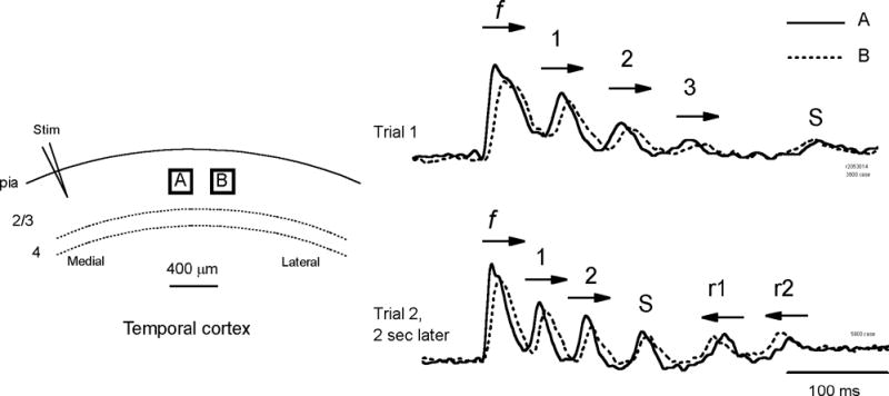
Figure 4.

Horizontal propagation of different oscillation cycles. Left: Optical detectors, A and B, are placed in layer II–III about 1.2 mm lateral to the stimulating electrode (Stim). Right: Optical signals from the two detectors are shown as solid (A) and broken lines (B) respectively, during two trials of evoked oscillations. Arrows on each cycle mark the horizontal propagation direction of the cycle. The direction was determined by the onset time for the waves arriving at the two detectors. The propagating direction of the first spike (f) was same for both trials, coming from the stimulation site and propagating to the lateral. In trial 1, three cycles following the first spike (1–3) had the same propagating direction, medial to lateral. At the end of trial 1 there may be another cycle (s) with direction indeterminate due to small amplitude. In trial 2 (evoked 2 seconds later) two cycles (1–2) had the medial to lateral direction but the other two (r1 and r2) had reversed propagating direction. One cycle, S, appeared to occur simultaneously on both detectors. Signals were filtered between 3–80 Hz.
