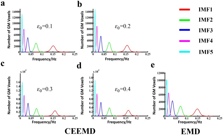
Fig 1. Histogram of frequency distribution using CEEMD and EMD, respectively.
From Fig 1a to Fig 1e, each figure represents the HWF distribution histogram determined from gray matter voxels in whole brain across the entire group of subjects (n = 161), with an input noise level ε0 of 0.1, 0.2, 0.3 and 0.4 using CEEMD as well as EMD respectively. The histograms of HWF of IMF1 to IMF5 were colored by red, green, blue, magenta and cyan respectively. The heights of the histograms represent the number of voxels whose HWF equals to the frequency on the horizontal axis.

