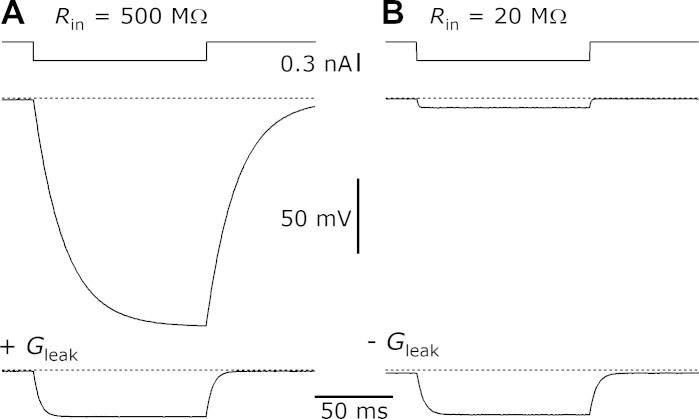
Fig. 3.
Current pass-through and leak conductance features of the dynamic clamp. Top traces: timing of 300-pA current pulses. Middle traces: changes in voltage measured in a 500-MΩ, 30-pF model cell (A) and a 20-MΩ, 30-pF model cell (B) using the dual-electrode recording setup. Bottom traces: responses of the model cells when an 8-nS leak conductance (Vrev = −75 mV; A) or a −40-nS leak conductance (Vrev = +15 mV; B) was added. Adding the leak conductance in A caused the time constant (τ) to accelerate and the amount of hyperpolarization to decrease. Subtracting the leak conductance in B caused the τ to decelerate and the hyperpolarization to increase. Rin, input resistance.

