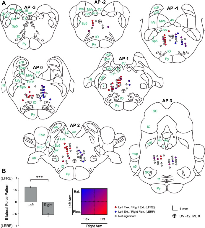
Fig. 10.
A: anatomical locations of stimulation sites with associated force response patterns. Brainstem sections were adapted from Szabo and Cowan (1984), with nomenclature from Martin and Bowden (1996). Colored circles represent a significant force response, with red representing a pattern of left-sided flexion and right-sided extension (LFRE), blue representing left-sided extension and right-sided flexion (LERF), and intermediate values defined by the color scale at the bottom. Gray circles indicate nonsignificant bilateral force responses. n4, Fourth cranial nerve; n5, fifth cranial nerve; 6, sixth cranial nerve nucleus; n7, seventh cranial nerve; 7, seventh cranial nerve nucleus; n8, eighth cranial nerve; 10, 10th cranial nerve nucleus; 12, 12th cranial nerve nucleus; icp, inferior cerebellar peduncle; mcp, middle cerebellar peduncle; scp, superior cerebellar peduncle; Py, pyramidal tract; tz, trapezoid body; IO, inferior olivary nucleus; SO, superior olivary nucleus; IVe, inferior vestibular nucleus; SVe, superior vestibular nucleus; LVe, lateral vestibular nucleus; MVe, medial vestibular nucleus; PrP, nucleus prepositus; ACu, anterior cuneate nucleus; Sol, nucleus solitarius; Pr5, principal nucleus of fifth cranial nerve; Sp5, spinal nucleus of fifth cranial nerve; LC, locus coeruleus; IC, inferior colliculus; SC, superior colliculus; 4V, fourth ventricle; Aq, cerebral aqueduct. The circle with crosshairs represents dorsoventral (DV) −12, mediolateral (ML) 0 in the stereotaxic coordinates. B: bilateral force output patterns by laterality of stimulation site (left vs. right). Output patterns corresponding to LFRE are closer to 1, and those corresponding to RFLE are closer to −1. ***P < 0.001. Error bars, SEM. [Fig. 10A adapted from Szabo and Cowan (1984). Reprinted with permission from Wiley. Copyright 1984.]

