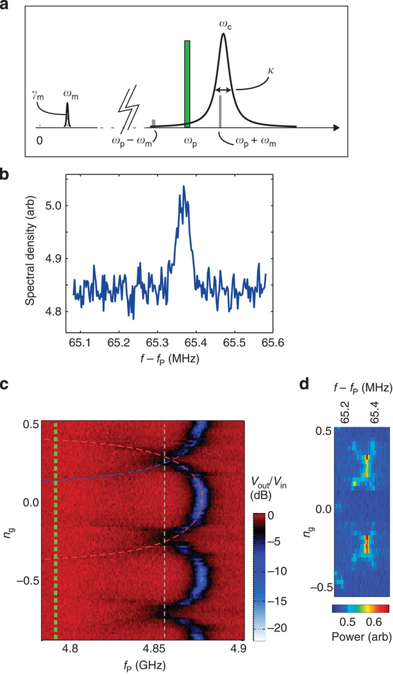
Figure 2. Basic characterization.
(a) The frequencies involved: the vertical axis gives the spectrum of either the cavity (ωc) or the mechanical resonator (ωm). The pump (frequency ωp) is applied around the detuning Δ≃−1 below the cavity frequency. (b) Thermal motion measured at 20 mK. The parameters are Δ≃−1, nc≃0.05, ng=0.25, Vg=6.5 V. (c) Gate charge modulation of the cavity resonance absorption. The resonance ωc(ng) of the effective cavity appears as the periodic black-blue line. The dashed red and blue lines are theoretical fits to two of the branches, obtained by using the qubit-cavity Hamiltonian17 in numerical diagonalization. The flux bias was Φ/Φ0≃0.39. The vertical green and grey lines represent the frequencies ωp and the sideband ωp+ωm, respectively, used to obtain the data in Fig. 3a,b. (d) Spectral density of the emission from the cavity around the mechanical sideband.

