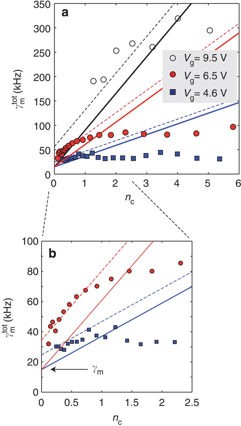
Figure 4. Nonlinear cavity damping.
(a) The total (tot) mechanical linewidth as a function of cavity photon number. Red circles: Vg=6.5 V, g0/2π≃0.7 MHz. Black circles: Vg=9.5 V yielding higher g0/2π≃1.0 MHz. Squares: smaller g0/2π≃0.5 MHz obtained with Vg=4.6 V. The solid lines are expectations from the basic linear model, that is  . The dashed lines include the qubit-induced extra linewidth,
  . (b) Zoom-in of the linear regime of a. In all the data, Δ≃−1, Φ/Φ0≃0.39.

